HOWTO
Use the OpenSceneGraph Exporter
for 3ds
max

1 Install the Exporter
Use the
setup.exe to install the plug-in. You should have 3ds max installed. The
plug-in is only tested on windows XP and windows 2000 with 3ds max 5.1. If you
are installing on windows98, you should add the install directory to your path
and reboot your computer. If you are having trouble loading the plug-in when
starting 3ds max, then try to load the plug-in directly from 3ds max. Open 3ds
max, press Customize -> Plug In Manager, right click the table with plug-ins
and press Load New Plug-in, find the install directory and choose OSGExp.dle.
2 Tools in the Exporter
With the
exporter come some tools:
- OSG Export Toolbar
- OSG Helper Objects
- fIVE Preview
2.1 OSG Export Toolbar
Under
Utilities (the hammer icon) -> More -> OSG Export Toolbar is a toolbar
for fast access to the exporter. The first button will preview full scene,
second button will preview selected objects. Third button will save to OSG file
format to the default export directory as exported.osg, fourth button will save
to the IVE format as exported.ive also in the default export directory; the
.ive format is only viewable with fIVE preview also installed with exporter.
The fifth button will let you control the export options, these will be save to
disk such that when reopening 3ds max and exporting again the same settings
will be used.
2.2 OSG Helper Objects
Under
Create (the icon with a mouse pointer and a star), choose the Helper icon (the
fifth icon from the left), and then select OpenSceneGraph in the drop down box.
Here you have access to more OSG related stuff. You are able to create
Billboards, LODs, Sequences, Switches, Occluder, and Imposters helper objects
and add geometry object to these. Sampling one geometry object over a period of
time can also make sequences. Further more you are able to add nodemasks to a
serie of geometry objects, and change stateset properties such as renderbin on
a particular set of geometry objects.
2.3 fIVE Preview
With the
exporter comes a preview function, really useful when changing the parameters
directly in the max model and previewing the result right away in OSG. In the
fIVE Preview you are able to change motion model, view wireframe, reset view,
save in IVE format, start/stop/pause animations and much more. Right click one
time in the preview window to find the menu for doing this. fIVE Preview is
also installed as separate program, fIVE.exe, which can run independently from
3ds max. By default install a shortcut on the desktop should lead you to it.
3 Introduction to the
Options Dialog
This
section will give a small introduction to the options dialog, which controls
the exporting.
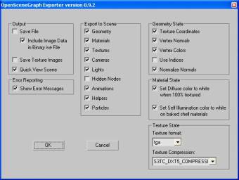
Above is a
picture of the dialog; it is separate into 6 sections:
- Output
- Error Reporting
- Export to Scene
- Geometry State
- Material State
- Texture State
These are
described in the following sections.
3.1 Output
Controls
the outcome of the exporting. Save it to a file or preview it with fIVE
Preview. If we are exporting .ive files, we can include imagery directly in the
file. When exporting to .osg files, the “Save Textures Images” should be
checked; the images will be saved in an “images” directory in the same
directory as the exported file is saved. When using the toolbar, there is no
need to use these settings, as these are set automatically. When exporting
without using the toolbar, you should select File->Export (selected) in 3ds
max. Choose directory to save to, and write name of file. If the name has the
ending .ive, it will be save in the IVE format, if the name ends on .osg it
will be saved in OSG format.
3.2 Error Reporting
Check this
option if you would like error reporting. When for instance exporting a
material, which uses a map channel, and there are not found any texture
coordinates on this mapping channel, when exporting some geometry having this
material assigned, an error will indicate it.
3.3 Export to Scene
This will
indicate what kind of objects that will be exported to the resulting .osg/.ive
file. If for instance no animations are wanted in the exported file then
uncheck this option.
3.4 Geometry State
Indicates
what should be exported with respect to the geometry state. If Vertex Normals
are unchecked, normals for every triangle will be exported instead. If Use
Indices is checked the resulting geometry, vertices/normals/texture
cords/colors, will be representing by arrays and indices. If Normalize Normals
is checked, GL_NORMALIZE will set to ON on every geometry object in the
exported file.
3.5 Material State
Indicates
what should be exported with respect material state. Check “Set diffuse color
to white 100% textured”, when a 3ds max material having a 100% diffuse texture
in the diffuse slot and you will not like the material colour to shine through
the texture. Check “Set Self Illumination color white on baked shell material”,
when a 3ds max shell material is used and you would like to have a white colour
in the self-illumination term.
3.6 Texture State
Indicates
what should be exported with respect to texture state. Here you can control the
image format of the textures. At present time the exporter can handle .tga,
.png, and .tiff. We are using 3ds max’s own plug-ins to write the images to
disk. If texture compression on the graphic card is needed, it is possible to
export arb compression, or dtx1, dtx3, dtx5 compression, or simply use no
compression by choosing the image data format.
4 Exporting Scenes
In this
section we will introduce you to some of the features, which are included in
the exporter. Every sub section here will indicate the feature, how to do it, a
link to a 3ds max file, and a screenshot.
4.1 Vertex Colours
Create a
geometry object, add a modifier called VertexPaint, and paint some colours on
it. Export it using the OSG Export Toolbar. File: vertexcolor.zip.
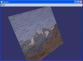
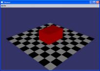
4.2 Blending Texture with
Geometry
Create a geometry object. Press M for the material dialog, press maps and diffuse slot, then two times click bitmap, find bitmap on disk and press ok. Find the materiel you applied the bitmap to. To the left of the diffuse slot is an amount box displaying the value 100%, turn this down to only 50 %. Give the material a colour of pure red. Attach material to geometry object by dragging the sphere from the material editor onto geometry object. Add an UVW Map modifier from the modifier list. Export using the OSG Export toolbar. File: blendtex.zip.
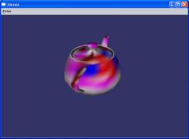
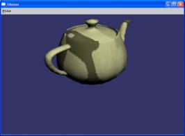
4.3 Procedural Textures
Create some
geometry. Create a new material; add a procedural texture to the diffuse slot,
like the Bricks Map for instance. Now add a UVW Mapping modifier to the object
and export using the toolbar. File: proceduraltex.zip.
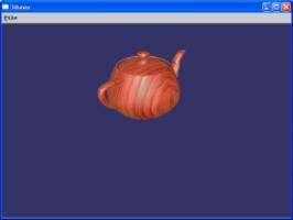
4.4 Procedural Textures
and Baked Materials
Create some
geometry; add a procedural texture to the diffuse slot, like a Marble Map for
instance. Assign the material to the geometry. Choose Rendering->Render To
Texture. Press add, choose Complete Map, and press Render. Export using the
toolbar. File: proceduraltexbaked.zip.
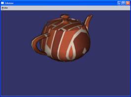
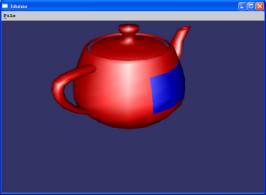
4.5 Multi/Sub Material
Create some
geometry. Press M for the material editor, and create a new Multi/Sub Object
Material. Let the first sub material be a red coloured, the second sub material
a blue coloured material, and assign the multi material to the geometry. Add a
mesh select modifier, and select some faces of the geometry. Add a material
modifier and choose Material ID 2 as parameter. Export using toolbar.
File: multimaterial.zip.
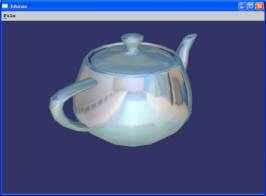
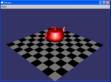
4.6 Environment Maps
You can use
any map as an environment map. All you need to do is create a new standard
material, add a map to the diffuse slot, check the environ box under the
Coordinates pane and assign the material to some geometry. Only Spherical
Environment is supported at present time. You can also add a map to the
Reflection slot in a standard materiel; this will give the same result. File: environment.zip.
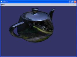
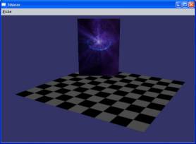
4.7 Cube Mapping
There two
approaches to making cube mapping in 3ds max: either you render the six images
from the current scene or you can use six already existing images. Create some
geometry. Create a new material, and add a Refract/Reflect map. Choose From
File as source, and find the six images by pressing the Up, Down, Left, Right,
Front, and Back slots. Assign the material to geometry and export. You can turn
down the cube mapping by setting the blend amount to 50% in the material editor
in the parameter field left to the Reflection slot. File: cubemapping.zip.
4.8 Composite Material
In the
composite material you can use any kind of materials that the exporter can
handle. You can render light maps, shadow maps, baked maps and put them all
together in the composite material. Notice, that it is only the texture
attributes in the sub materials, which are used in the composite material. When
blending the materials in the composite material, you have four possibilities:
A, S, M, or blend amount. When using A the texture is Added to the previous
colour/texture, when using S the texture is Subtracted from the previous
colour/texture. Using M will Multiply with the previous colour/texture. If a
value different than 100% is found in the spinner field, neither A, S, or M is
used, but then we simply blend the previous colour/texture with the amount
given in the field.
Create some
geometry. Press M for the material editor. Create a composite material. Create
the first sub material, add a Brick Map to the diffuse slot, and set the map
channel to 1. Add a UVW Mapping modifier, set it to use map channel 1, and set
the U and V tile to 3. Create a second sub material, add a bitmap map to the
diffuse slot, and set the map channel to 2. Add another UVW Mapping modifier,
and set it to use map channel 2. Add the Composite material to the geometry;
set first sub material to 50%, set second sub material to 50 %, and export.
File: composite.zip.
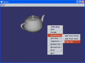
4.9 Camera
Create some
geometry. Press the camera icon and choose a target camera. Using the mouse
place the camera and target in a good position and export using the toolbar.
Right click in the fIVE Preview window to active the menu and move the mouse to
the ViewPoints menu entry. Here will all cameras created in 3ds max be listed.
Choose a camera entry to jump to that position. File: camera.zip.
4.10 Lights
The
Exporter supports four kinds of lights found in 3ds max:
- Target/Free Spot
- The cut off value in OSG is
set to half the size of the falloff value found in 3ds max.
- The spot exponent in OSG is
set to the difference between the falloff and the hotspot value found in
3ds max.
- Directional Light
- The last value in the light
position in OSG, w, is set to zero such that the light is treated as
directional in openGL.
- Omni light
- The direction of the light in
OSG is set to (0,0,0), in this way the light is treated as an omni light
in openGL.
If the 3ds
max light is located in the root node, it will be treated as a global light in
OSG and never culled away. If located in the other places than the root node,
the light will be culled away just like any other kind of geometry.
Create some
geometry in 3ds max. Press the light icon and choose one or more of the
Target/Free Spot, Target Direct, or Omni lights. Place the lights in some good
positions and export using the toolbar. File:lights.zip.
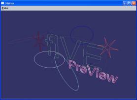
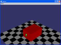
4.11 Shapes
Go to the
shape icon, the icon right next to the create icon you normally use when
creating boxes, spheres, planes, etc. Here you can use all the different kinds
of shapes: text, star, ellipse, rectangle etc. If you create a shape, select
the modify pane, extend the Rendering table and choose Display Render Mesh, you
can change for instance the thickness of the shape. This is done with the
PreView text in the picture below. Export using the toolbar. File: shapes.zip.
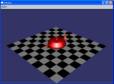
4.12 Simple Particles
In the
exporter we have support for simple particle systems. Here you can use the snow
or the spray particle system from 3ds max. To create a particle system choose
Particle Systems from the dropdown list right below the create, shape and
lights icons. Choose for instance the snow particle system and place it in the
scene, create some additional geometry in the scene. You can change count, size
of the flakes, speed, variation, etc. for the particle system. Further more,
you can also add a material with texture to the particle system. File: particles.zip.
4.13 Simple Animation
Create some
geometry. Press the “set key” button in the bottom pane of 3ds max. Select the
geometry you want to animate, and press the big key icon button to record the
initial stating position of your animation. If the key button is not activated
then press escape. Move the time slider to another position and
translate/rotate/scale your geometry into the position your want. Press the key
button to record this position. Keep on doing this until your animation is
done. Export using the toolbar by pressing the first button. File: animation.zip.
|
|
|
|
|
|
4.14 Billboard
Create some
geometry. Press the helper icon and choose the “OpenSceneGraph” entry from the
drop down list (see section 2.2 for more info on OSG helper objects). Press the
Billboard button and place a new OSG_Billboard object in the scene. Make sure
the OSG_Billboard object is selected and go to the modify pane. Press the Add
or the Add Multiple button to select the geometry you would like to add to this
billboard object. Export using the toolbar. File: billboard.zip.
4.15 LOD
Create some
geometry. Press the helper icon and choose “OpenSceneGraph” from the dropdown
list. Press the LOD button and place a new OSG_LOD object in the scene. Select
the OSG_LOD object and go to the modify pane. Press the first None button and
add the first geometry object which is going to be part of this LOD. Fill out
the minimum and maximum values to indicate in which range the object is going
to be visible. The values given in the minimum and maximum range is passed
directly into the LOD object created in OSG, hence there is no unit conversion.
Export using the toolbar. File: lod.zip.
|
|
|
|
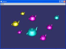
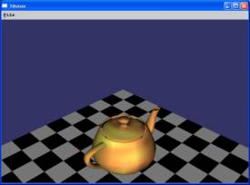
4.16 Impostor
Create some
geometry. Press the helper icon and choose “OpenSceneGraph” from the dropdown
list. Press the Impostor button and place it in the scene. Select the
OSG_Impostor object if not already selected and go to the modify pane. Press
the Add or the Add Multiple button and add some geometry to the impostor
object. Export using the toolbar. All the teapots presented in the picture
below are impostors; they are simple quads with textures on. File: impostor.zip.
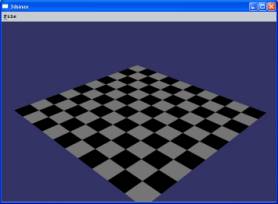
4.17 Occluder
Create some
geometry. Create and place a closed shape, a rectangle for instance, to
represent the occluding shape. Go to the helper icon and choose
“OpenSceneGraph” from the dropdown list. Press the Occluder button and place
the OSG_Occluder object in the scene. Select the OSG_Occluder object if not
already selected and go to the modify pane. Add the occluding shape to the
OSG_Occluder object by pressing Add. Export using the toolbar. Whenever the
occluding shape is in front of the object, the object is not visible (culled
away from the scene). Whenever just a small part of the objects is out of the
occluding shape the object is visible. File: occluder.zip.
|
|
|
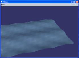
4.18 Sequence
With the
OSG sequence helper object you can do two things: sample a single object over a
period of time or specific up to five objects to represent a sequence.
To sample
some geometry into a sequence, you will need to create some geometry and for
instance add a mesh modifier. Over a period of time you can change the mesh
modifier in the curve editor in 3ds max. You then go to helper icon and choose
“OpenSceneGraph” from the drop down list. Press the Sequence button and place
an OSG_Sequence object in the scene. Select the OSG_Sequence object and go to
the modify pane. Add your mesh-modified geometry to the OSG_Sequence object by
pressing the button just below the text “Sample Geometry”. Export using the
toolbar. File: wave.zip.
|
|
|
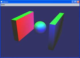
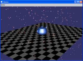
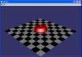
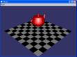
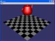
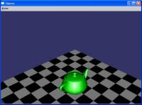
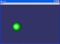
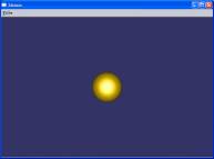
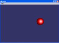
To make a
sequence from a number of geometry objects instead, you create the geometry
objects and create an OSG_Sequence objects as described above. Select the newly
created OSG_Sequence object and go to the modify pane. Choose “Use Static
Geometry” in the OSG_Sequence object and press the “None” buttons below to add
the geometry objects. You can specify the frame time for each of the geometry
objects. If you want the geometry objects to be shown 1 second after each
other, you type 1 second in all the “Frame Time” input fields. In the example
given here, the green sphere is shown in 1 second, then the yellow sphere is
then shown in 1 second, and finally the red sphere is shown in 1 second. File sequence.zip.
|
|
|
|
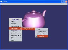
4.19 Switch
Create some
geometry. Press the helper icon and select “OpenSceneGraph” from the dropdown
list.
Press the
switch button and place the OSG_Switch object in the scene. Go to the modify
pane to add some geometry to the switch. Press the Add or Add Multiple button
to add the geometry. Export using the toolbar. In the fIVE Preview you can
switch among the different objects by right clicking and selecting the
“Switches” menu entry. File switch.zip.
4.20 StateSet
The
StateSet helper object in the exporter was mainly created to assign objects to
different renderbins. Renderbins in OSG is used to specify which objects are
going to be drawn first. So if you would like an object always to be drawn
last, you can give it a high renderbin number using the OSG StateSet helper
object in 3ds max.
4.21 NodeMask
The
NodeMask helper object in the exporter was created to assign nodemasks to
geometry objects. This is especially useful if there is going to be
intersection tests in the exported scene.